Rotary Jet Mixer NK-T700S
EQUIPMENT DESCRIPTION
Principle : The principle of this equipment is to prevent the accumulation of sludge on the bottom of the crude oil storage tank using high discharging oil circulating pump, Win’s rotary jet mixer. The high discharge pressure of jet mixer breaks the sludge into small pieces after which the sludge is decomposed and dissolved in the crude oil while the sludge floats up.
Characteristics of crude oil storage tank and sludge
Oil storage tank : The asphalt, tar, wax, etc. in the crude oil deposit on the bottom of the tank while the oil is stored in the tank and these deposits become high viscosity sludge. It is hard to remove the sludge except mechanical crushing or chemical dissolving methods. Due to the oil washing system, all sediments such as rust, scale, mud, sand, etc. in the cargo oil tank flow into the storage tank.
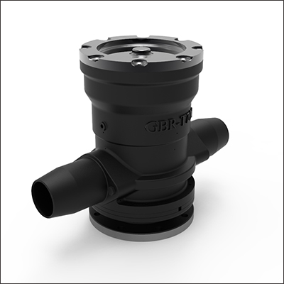
MODEL NAME : NK-T700S
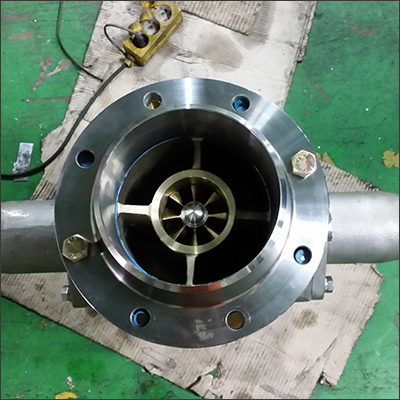
NK-T700S PHOTO
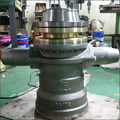
NK-T700S PHOTO
Sludge : The sludge contains 80-90% of oil and wax which are useful to recycle. Depending on the place of the oil production, oil contains inorganic substances such as sand, mud, iron; sludge containing oil, water, emulsion; organic substances such as oil, wax and asphalt. If these compositions of sludge sediment on the bottom of oil tank, the following problems will occur.
– Reduction of tank storage capacity. – Corrosion of tank bottom due to the water in the sludge.
– Incorrect gauging of tank. – Increased cost for maintenance, repair and cleaning.
– Potential risk in case of floating roof. – Disposition of sludge when inspecting open tank.
KEY PARAMETER
| DESCRIPTION | SPECFICATION |
| NOZZLE SIZE | Ø55, Ø70, Ø85, Ø100, Ø115 |
| IMPALLER | 15°, 30°, 45° |
| HEIGHT (H) | 550 mm |
| WIDTH (W) | 750 mm |
| WEIGHT | 200 Kg |
| CONNECTION | 6” or 8″ ANSI 150# R.F |
MATERIALS AND PRODUCT STRUCTURE
| NO | DESCRIPTION | SPECFICATION |
| 1 | IMPELLER | ALUMINUM BRONZE |
| 2 | MAIN BODY | STAINLESS STEEL |
| 3 | NOZZLE | STAINLESS STEEL |
| 4 | IMPELLER SHAFT | STAINLESS STEEL |
| 5 | GEAR BOX | STAINLESS STEEL |
| 6 | GEAR COMPONENTS | STAINLESS STEEL & SM |
Type of machine
Central type
The center-mounted machine is designed to be placed on the tank floor in the centre on the tank. Both nozzles normally would discharge simultaneously through the entire 360°rotation of the machine. One nozzle of the JET-MIXER can be blanked off to accommodate pump flow rate limitations. Single-nozzle operation requires that the installation be designed to withstand jet reaction. This installation can only be considered in a clean, gas free, tank since it is necessary to conduct ‘hot’ work.
Shell type
The shell-mounted JET-MIXER is designed to be placed at the tank wall, using the existing tank shell man
way for mounting. Only the nozzle facing away from the tank shell discharges as the machine continuously rotates in a clockwise
direction. An internal baffle (see Figure 1.1) prevents the nozzle facing the tank shell from discharging. The flow ‘change over’ between the nozzles is smooth and commences when the nozzles are approximately tangential to the tank shell. Flow from one nozzles is gradually reduced as flow to the other is increased proportionally to begin the cleaning cycle again. The shell-mounted JET-MIXER can be installed in a tank that is in service provided the man way door can be removed for installation. Unlike the centre-mounted JET-MIXER, the shell-mounted machine does not require any ‘hot’ work for installation. The shell-mounted JET-MIXER affords ease of access for maintenance and the installation can be either portable or permanent.
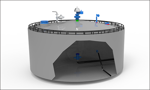
CENTER MOUNTED TYPE
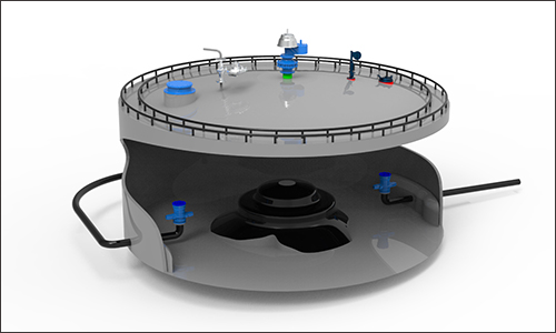
SHELL MOUNTED TYPE
Test and inspection
① Test procedures
– Purchaser shall specify the attendance in the inspection and test.
– Test and inspection items of jet mixer are as follows and the attendance of purchaser shall be as specified as
below.
• Appearance and dimension inspection (witness)
• Performance test (witness) (model test)
– Rotating speed inspection
– Spraying speed inspection
– Spray distance
• Hydraulic test (witness)
② Hydraulic test
– Pressure applied part in the jet mixer should be hydraulic tested under 1.5 times of the maximum permissible
operation pressure.
– Test should be carried out for sufficient time under pressure to completely investigate all parts. Hydraulic test
should be carried out for more than 30 minutes and there should be no fluid flow in and leakage.
– The fluid for hydraulic test should be pure water of which temperature is below 40℃. If the specific gravity of
the used fluid is not the same as the specific gravity of the pure water, compensate the test results to match with
the specific gravity of the used fluid.
③ Performance test
– The performance test of jet mixer is a model test in principle using simple test facility. But the test results
should satisfy the standard of performance.
– Example of operation conditions for model test.
Set the inlet pressure of jet mixer at 3.5-4.5 ㎏/㎠ and flow rate at 450-610 ㎥/h. Properly mark on the rotating
part of jet mixer before switch on pump. Rotate the pump for a certain period of time and record the pump
operation hours. Calculate the rotation feeding distance and rotating angle. The results should be 0.58 – 0.78°.
Measure the diameter of spray nozzle and calculate the cross sectional area. Using the flow rate in the flow
meter, the spray speed at nozzle outlet should be 15-22m/s. Under the above pressure and flow for a certain
period of time, the spray distance should be 12-17 m.
