Vacuum Relief Valve NK-BV11 Series
INTRODUCTION
Vacuum relief valves are used on liquid storage tanks and other process vessels or systems to prevent structural damage due to excess internal vacuum. Storage tanks are pressurized when liquid is pumped in, compressing the existing vapor or when rising temperatures cause increased evaporation or expansion of existing vapor.
Conversely, a vacuum condition may be created when pumping out or due to falling temperature. To prevent tank damage, vapor must be allowed into or out of the tank at specified vacuum condition. The volume rate of venting depends upon the tank size, volatility of the tank contents, the pumping rates and the temperature.
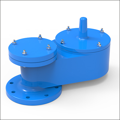
MODEL NAME : NK-BV11 SERIES
DESIGN AND FUNCTION
|
Model No. |
Type | Material |
Setting Pressure Range |
|
NK-BV11W |
Weight Loaded release to ATM | Aluminum, Carbon Steel, Stainless Steel |
22 ~ 700 mmH2O |
|
NK-BV11S |
Spring Loaded to ATM | Aluminum, Carbon Steel, Stainless Steel |
Above 700 mmH2O |
Note) Other specification to be consult by factory.
Tank protection equipment typically includes an operating valve which is designed to provide pressure relief under normal pump in thermal breathing conditions.
Vacuum Relief
As a vacuum is drawn in the storage tank (for example, when fluid is being pumped out). When the vacuum setting is reached, the pallet lifts and air is drawn in the storage tank from the atmosphere. Model NK-BV11, NK-BV14 is designed for vacuum relief only. It has housing body and drip rings to protect seating surfaces from condensation and freezing. Valve size must be selected to perform required vacuum relief under operating and normal thermal conditions. Model NK-BV14 may be side mounted on the tank body or pipe away.
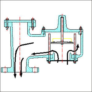
MODEL NAME : NK-BV11W
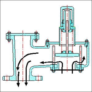
MODEL NAME : NK-BV11S

MODEL NAME : NK-BV13W
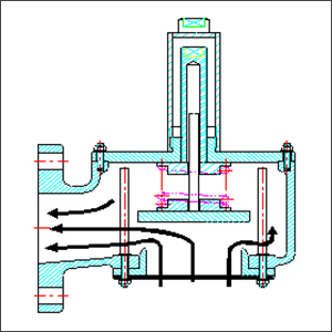
MODEL NAME : NK-BV13S
INSPECTION AND STORAGE
The vacuum relief valve is carefully packaged to prevent damage or contamination during shipping. Inspect all equipment when it is received: report any damage to the carrier immediately.
The valve should be protected during handling and storage. Keep all the ports plugged to prevent intrusion of foreign materials. Before installation, inspect the unit for indications of physical damage or internal contamination. If these are observed, the valve must be disassembled, cleaned and repaired before installation.
DRAWING AND DIMENSION
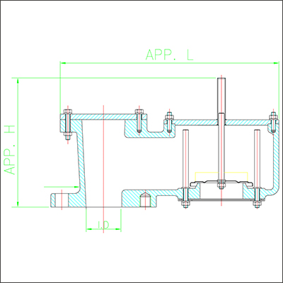
| 2” | 3” | 4” | 6” | 8” | 10” |
12” |
|
|
N.D |
50 | 80 | 100 | 150 | 200 | 250 |
300 |
|
H |
235 | 265 | 335 | 435 | 480 | 525 |
610 |
|
L |
315 | 285 | 435 | 555 | 675 | 770 |
885 |
UNIT : mm
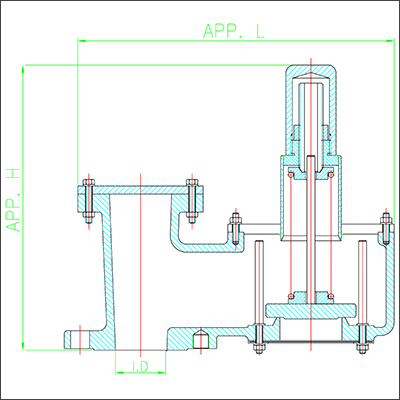
|
2” |
3” | 4” | 6” | 8” | 10” |
12” |
|
|
N.D |
50 | 80 | 100 | 150 | 200 | 250 |
300 |
|
H |
235 | 350 | 420 | 500 | 528 | 660 |
790 |
|
L |
315 | 385 | 435 | 555 | 675 | 770 |
885 |
UNIT : mm
